Caldera's electric steam system for industrial sites
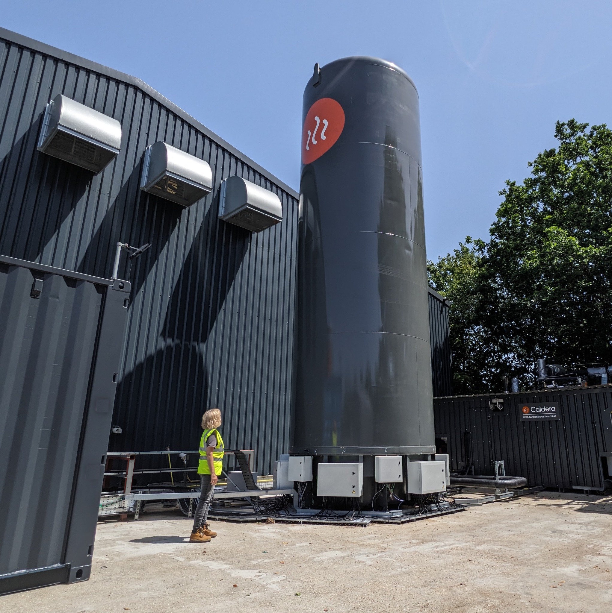
The Caldera Storage Boiler supplies saturated steam up to 204°C for industrial processes. It can connect into a site's existing steam network, or be used in new builds, delivering steam as a steady supply or to meet rapid peaks.
< 1 s
< 60 s
16 barg
> 95%
94%
> 20 years
It starts with the Heat Cell
The Heat Cell is the heart of the Storage Boiler, where heat is generated, stored and used to raise steam. Each cell contains a thermal core, base and insulated cover.
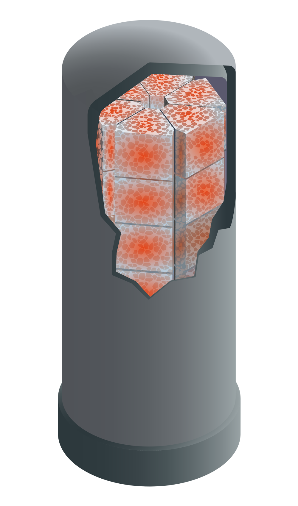
Thermal media blocks contain integrated heating elements and embedded steam pipework, so the Heat Cell charges electrically and generates steam within the core.
The base encloses the pumps, valves and service components that control water flow through the Heat Cell and regulate steam output
The cover encloses the thermal core and uses Caldera's proprietary vacuum insulation to minimise heat loss and avoid site-applied cladding.
In operation
Resistive elements in the blocks heat the metal to a maximum of 500°C; thyristors vary charging power.
Water flows through embedded coils until the blocks cool to 250°C; pump speed controls discharge rate.
Core material
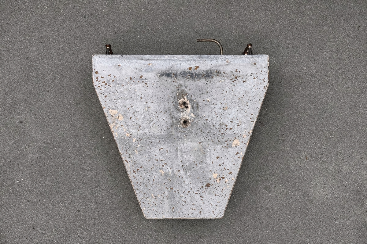
The thermal core is built from iron pellets set in a recycled-aluminium block. The metal is dense, durable and highly conductive, so heat from the embedded elements spreads evenly and the core charges far faster than alternatives such as sand, brick or concrete.

Vacuum cover
Each thermal core sits inside a double-walled vacuum vessel. With no gas between the walls, heat cannot escape by conduction or convection, and a proprietary inner layer suppresses radiative loss. The cover holds its heat for days and needs no additional cladding.
Water treatment
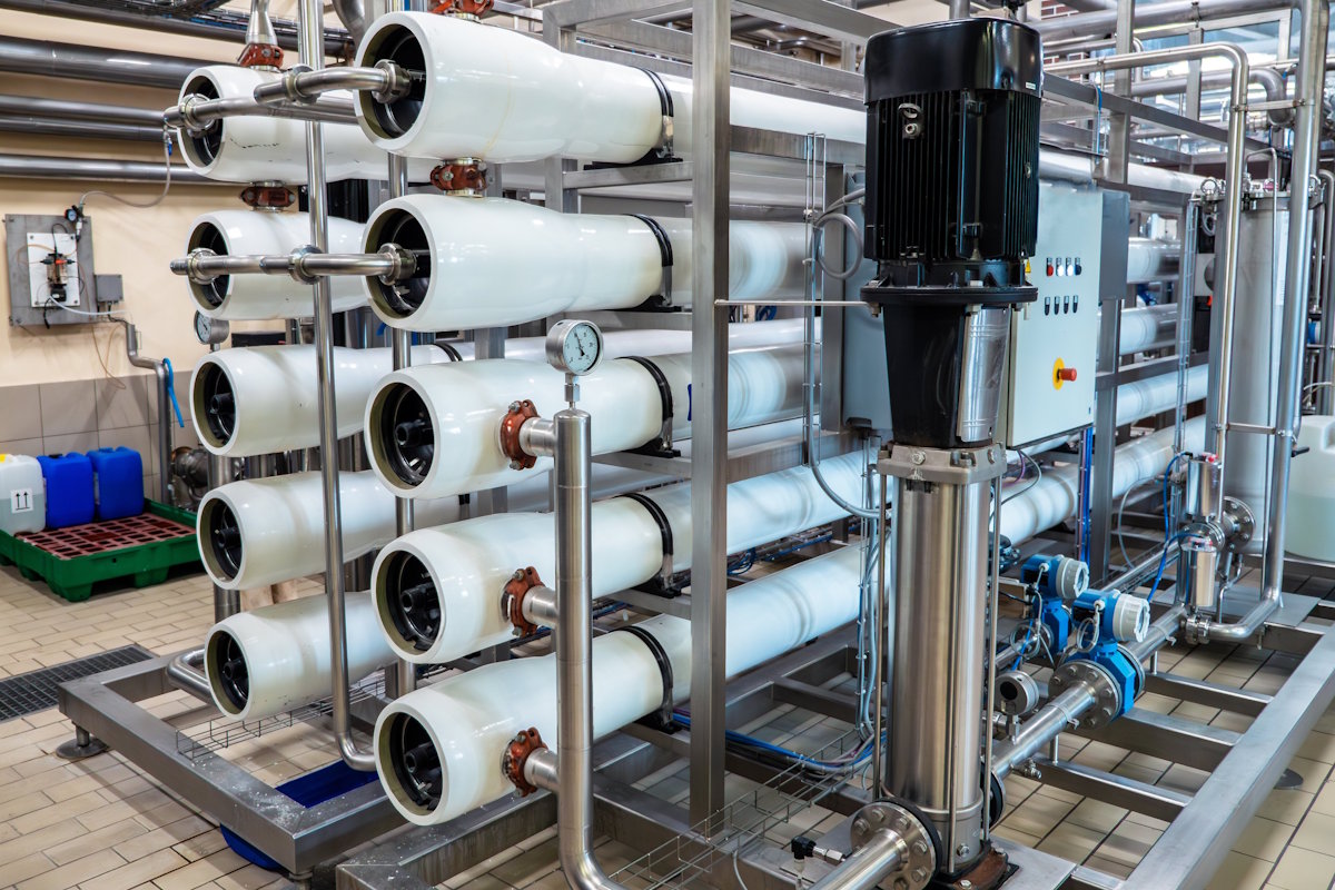
Before water enters the Heat Cell it is treated to the quality required for reliable steam generation, avoiding minerals and impurities that could cause scale or corrosion. The exact design depends on the site's existing water supply, condensate return and treatment arrangements.
Smart controls
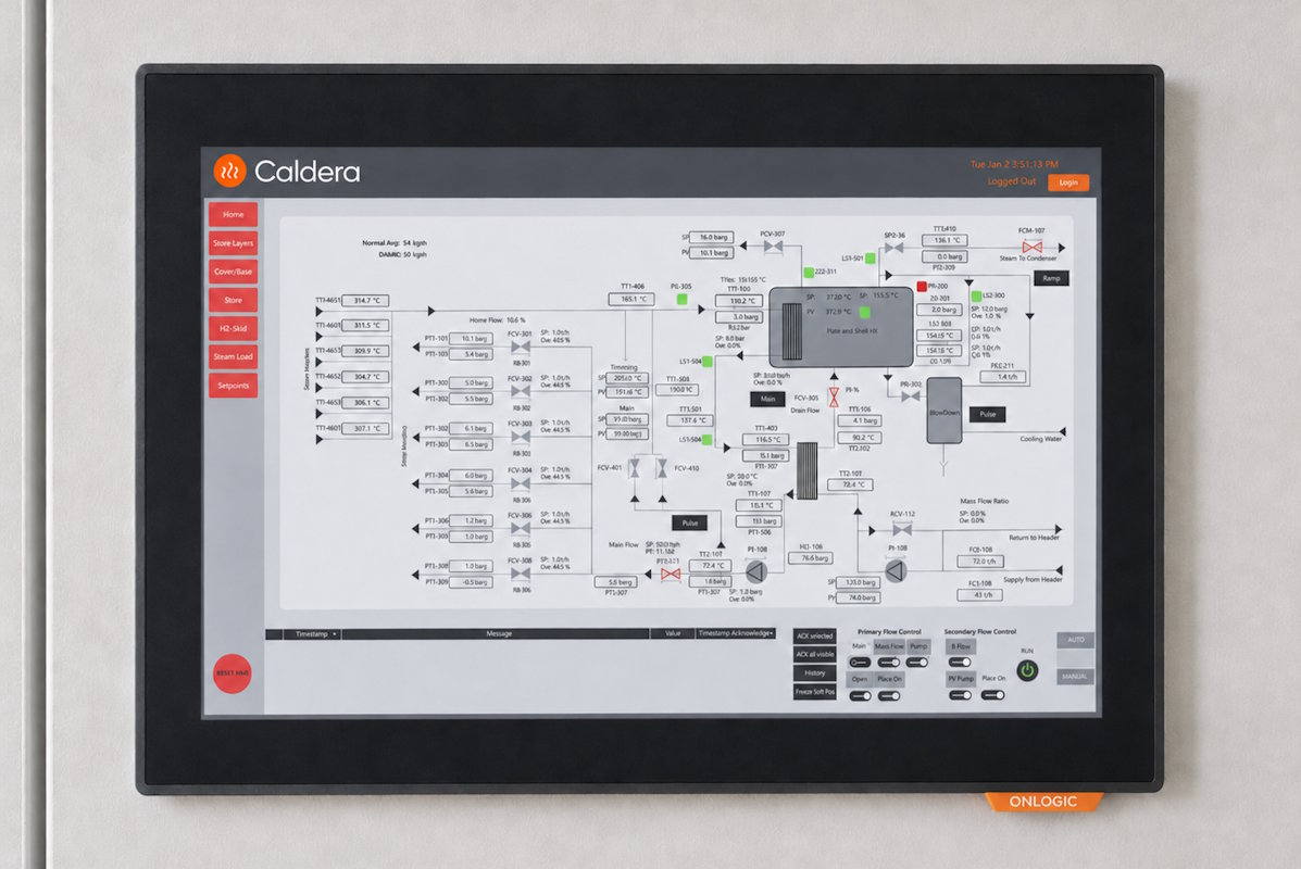
A Siemens PLC manages when the system charges, how it operates within site grid-connection limits, and how it responds to steam demand. It can monitor electrical import so the Storage Boiler never overloads the connection, and connect to optimisation platforms for cheapest-power and flexibility signals.

Power system
The power system links the Storage Boiler to the site's medium-voltage supply, at 11, 20 or 33 kV, and steps it down to 690 V to drive the resistive heating elements. A thyristor controller varies charge power continuously from 0 to 100% with sub-second switching, so the Storage Boiler can ramp quickly to follow electricity prices and grid signals while staying within the site's connection limit.
Turnkey solution
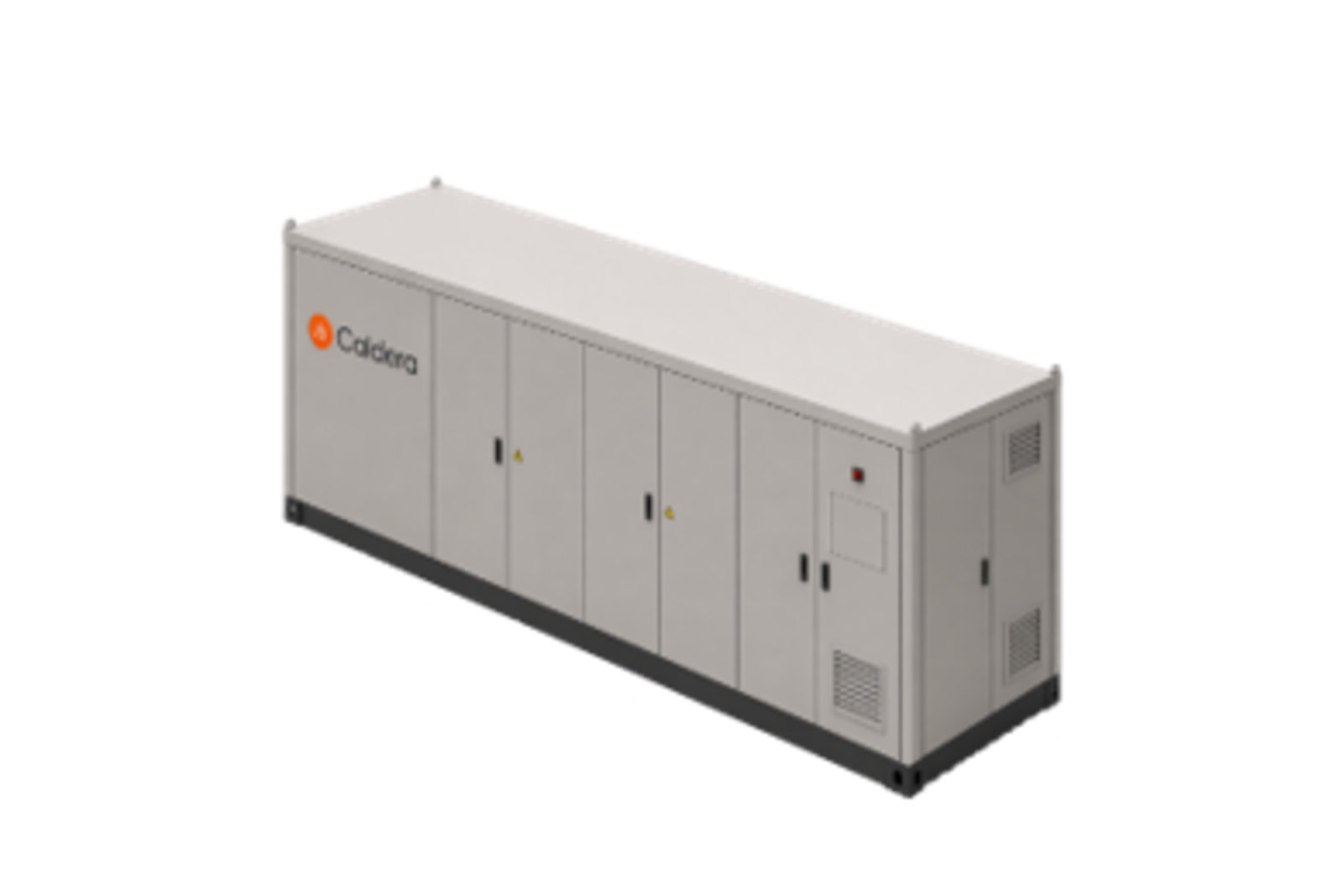
Caldera's scope of supply covers the complete Storage Boiler. This includes the proprietary heat cell, alongside sub-assemblies for water treatment and power. Each sub-assembly in the Storage Boiler is designed to be factory-built and tested, ready for road transport. This enables rapid, reliable on-site assembly before commissioning.


Scaling the system
The system can be scaled to meet the requirements of almost any site. The two example configurations show how Heat Cell count affects capacity, charge rate and maximum discharge.
Site integration
In a retrofit installation, the Storage Boiler supplies steam into the existing header. Existing gas, oil or LPG boilers can remain for backup, peaks or transition. The system targets a set pressure in the steam network, governing how it works alongside existing plant.

Discuss your steam system
The Caldera team can model your heat demand, assess integration with your existing setup, and talk through system design.


